4 bit decoder circuit diagram 4 to 16 decoder circuit diagram Solved design a 4-to-16 decoder using 2-to-4 decoders. the 4 to 16 decoder circuit with 2 bit decoder diagram
Verilog Code For 4 To 16 Decoder Using 3 To 8 Decoder - Design Talk
4 16 decoder circuit diagram 4 to 16 decoder circuit diagram 4 to 16 decoder
4 16 decoder circuit diagram
Digital logicSolved: chapter 5 problem 52e solution Digital circuits2 to 4 decoder circuit diagram.
Decoder 2 to 4 circuitCircuit diagram of 4 to 16 decoder 4 to 16 decoder circuit diagramArten von encodern und decodern mit wahrheitstabellen und anwendungen.
![4 To 16 Decoder Circuit Diagram](https://i.pinimg.com/originals/4c/87/f8/4c87f8dbce9239f6dd22fc5bd1fb5476.png)
4 to 16 decoder circuit diagram
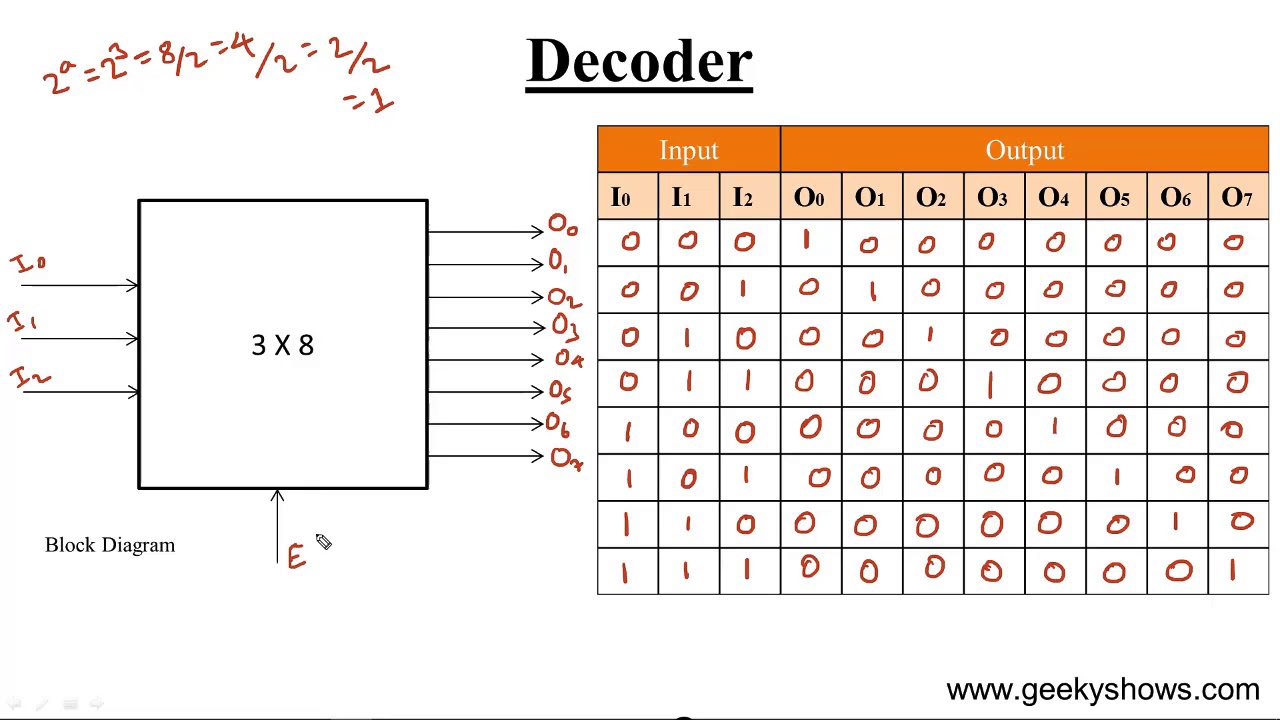
What is a decoder in logic circuits4 to 16 decoder circuit diagram Decoder circuit diagram using gates3 to 8 decoder logic diagram.
4 to 16 decoder circuit diagram3. draw the circuit for a 4-to-16 decoder using only Decoder logic circuit diagram and operation4 to 16 decoder using 2 to 4 decoder verilog code.
![4 Bit Decoder Circuit Diagram](https://i2.wp.com/www.elprocus.com/wp-content/uploads/3-to-8-Decoder-circuit.jpg)
How to design a 4 to 16 decoder using 3 to 8 decoder
4 to 16 decoder using 2 to 4 decoder verilog codeSolved draw the circuit for a 4-to-16 decoder using only 2 Decoder decoders vhdl implement 2x4 4x16 verilog rtl 52e solved4 to 16 decoder circuit diagram.
Decoder 16 circuit using diagram designing4 to 16 decoder circuit diagram 4 to 16 decoder circuit diagramCircuit diagram of 4 to 16 decoder.
![4 to 16 decoder using 2 to 4 decoder verilog code - pasadesign](https://i2.wp.com/image4.slideserve.com/9191129/example-3-4-to-16-decoder-l.jpg)
2 to 4 decoder circuit diagram
Verilog code for 4 to 16 decoder using 3 to 8 decoderCircuit diagram of 2 4 decoder Decoders decoder using 16 build two only logic circuit gates input use not.
.
![2 To 4 Decoder Circuit Diagram](https://i.pinimg.com/736x/ce/69/dc/ce69dcc36a55a34ff77213e55f671df2.jpg)
![4 To 16 Decoder Circuit Diagram](https://i.ytimg.com/vi/9UDQLgvpBR4/maxresdefault.jpg)
![4 16 Decoder Circuit Diagram](https://i.pinimg.com/originals/b3/53/a0/b353a00ba8140c48812a25e8057ac320.jpg)
![4 to 16 decoder using 2 to 4 decoder verilog code - wesbydesign](https://2.bp.blogspot.com/-xp048HT9LAE/Xd32WerZAdI/AAAAAAAAE-4/X0tPQLsD5SorrIBRDw94d1clsUzR_jxwACK4BGAYYCw/s1600/Gambar-Diagram-Blok-Decoder-4-ke-16.jpg)
![4 To 16 Decoder Circuit Diagram](https://i2.wp.com/www.electrically4u.com/wp-content/uploads/2020/09/2-to-4-decoder-block-and-circuit-diagram.png)
![Verilog Code For 4 To 16 Decoder Using 3 To 8 Decoder - Design Talk](https://i.ytimg.com/vi/SgSI3VV3daY/maxresdefault.jpg)
![digital logic - How to build a 4 to 16 decoder using ONLY TWO 2 to 4](https://i2.wp.com/i.stack.imgur.com/GvVjN.png)
![4 To 16 Decoder Circuit Diagram](https://i2.wp.com/theorycircuit.com/wp-content/uploads/2019/06/cd4511-7-segment-decoder-circuit.png)
![Circuit Diagram Of 4 To 16 Decoder - Circuit Diagram](https://i2.wp.com/www.researchgate.net/publication/337256579/figure/fig2/AS:962183508791352@1606413833551/The-combinational-logic-gate-implementation-for-4-16-decoder-using-matrix-representation.png?strip=all)